Inspection and
dimensional control
In real-time
inspection
and dimensional control?
- Avoids the extra cost of traditional in-line control, thanks to the reliability and robustness of automated control.
- Guarantees production rate despite the presence of on-line control. The result is instantaneous, enabling you to interact with the manufacturing process very quickly.
- Control of material shortages or surpluses
- Dimensional control
- Measurement of shape defects
The complete process
Step 1: DIGITIZATION
From real to virtual
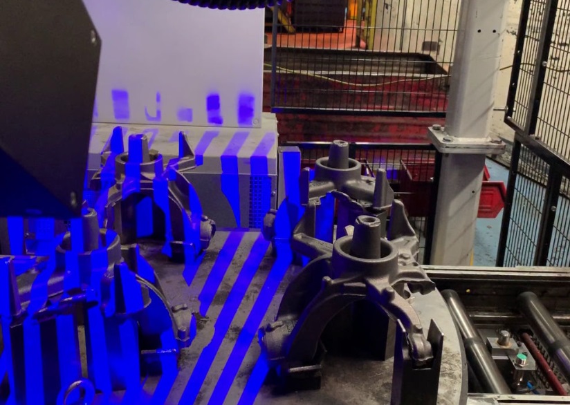
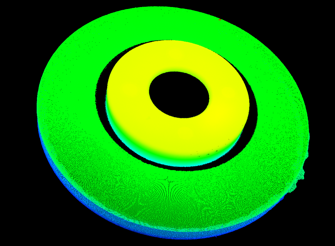
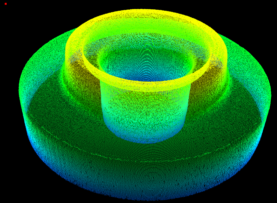
The Cirrus3D camera digitizes the actual work scene in the form of a 3D cloud of points. The sensor uses stereovision technology for data acquisition, ensuring the quality of the information contained in the scan for maximum performance in scanning results. The user can graphically define the parameters of the working scene: working volume, density of points contained in the point cloud.
Step 2: PREPARING THE ANALYSIS
Quickly and easily
Import of the cloud of points and CAD, creation of markers and CAD alignment, point cloud filtering... All preparatory analysis steps are automated. Program creation is carried out entirely via a graphical interface, without the need to write a single line of code. Simply create your program on your reference part and run your automated analysis on subsequent parts.
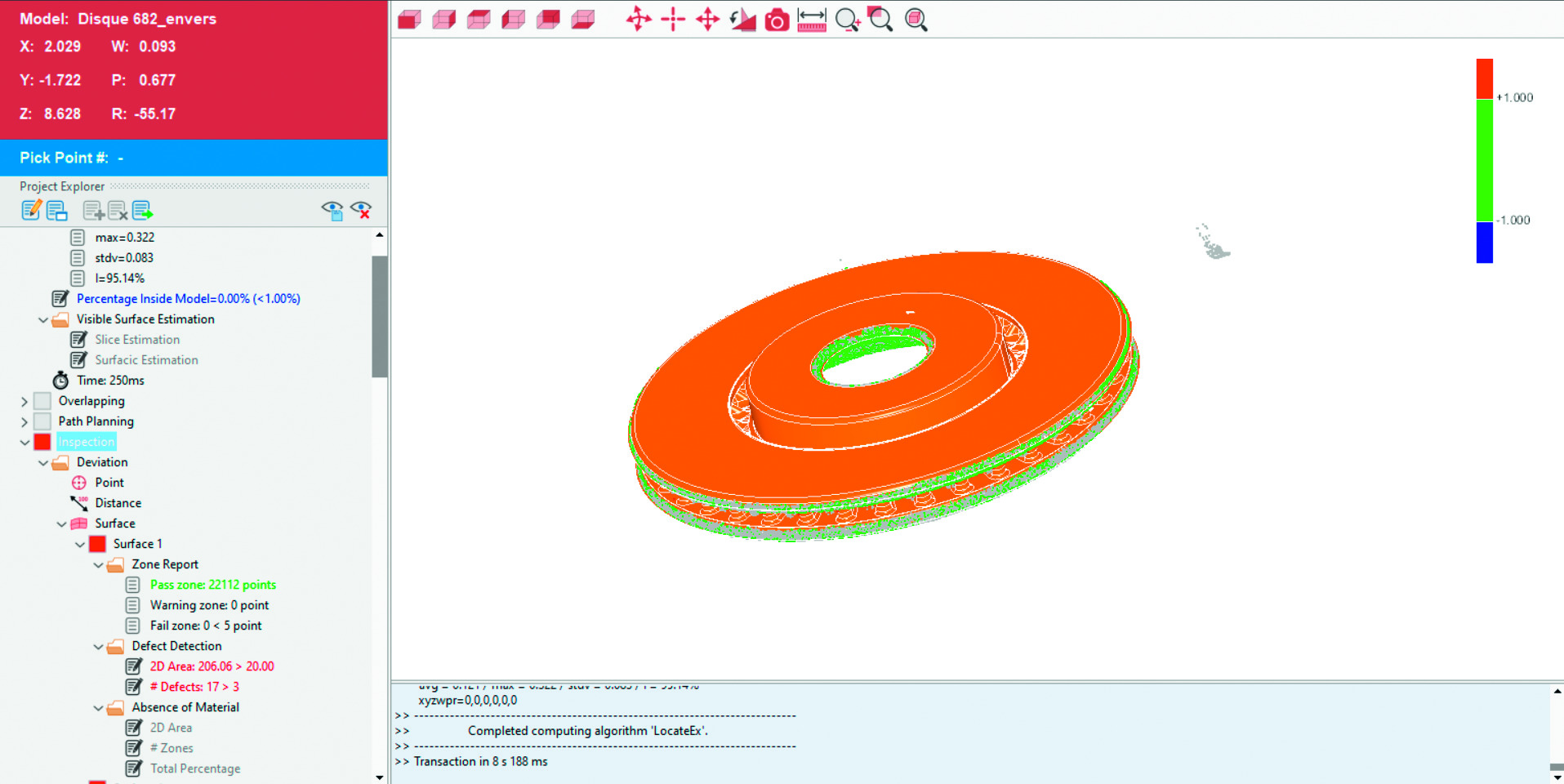
Step 3: MEASUREMENT
Metrologically or by attribute
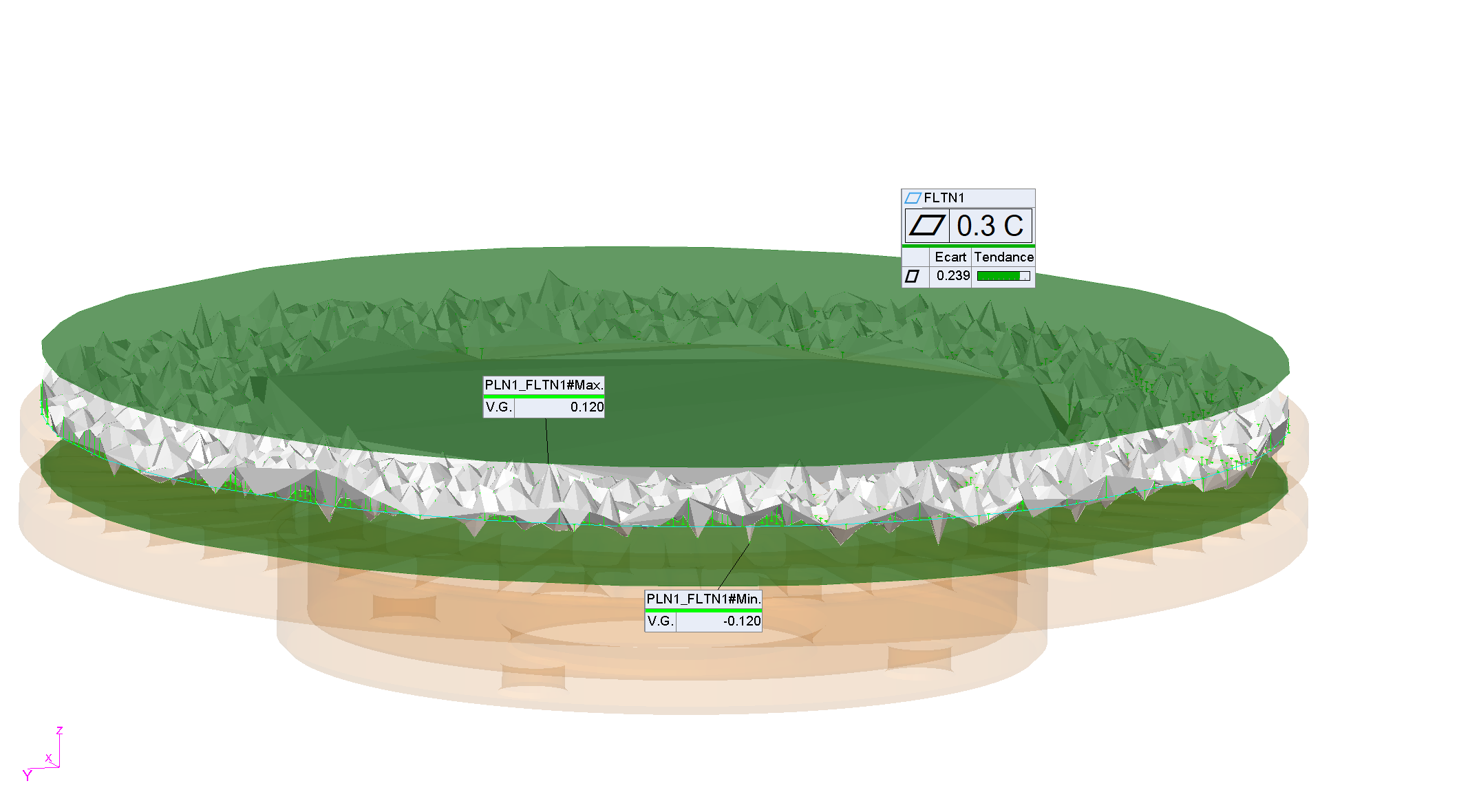
Measurement of geometric or surface elements, inspection of clearances and flushes, thickness evaluation... all the usual measurements can be easily addressed. Each type of element has a series of individual extraction strategies to address the most complex measurement scenarios.
During the programming phase, extraction zones and parameters are dynamically displayed in the 3D window. The parametric architecture of the software allows live control of the impact of each variable on the result of the measured element.
Step 4: RESULTS AND MEASUREMENT TOLERANCING
In just a few clicks
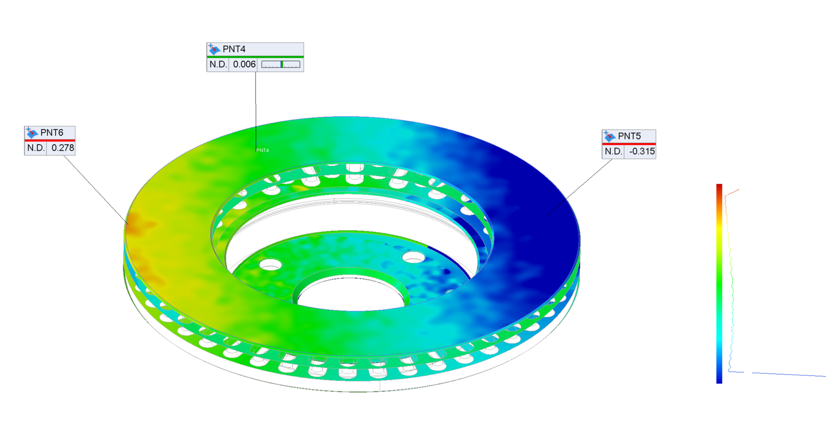
The image processing software features the most powerful and automated tolerancing engine on the market. As a user, all you have to do is fill in the tolerance cartridge as it appears on your drawing. The software applies all the calculation and optimization criteria specified by the latest versions of ISO and ASME standards.
As with geometric and surface elements, geometric tolerances can be isolated in detailed 3D views. This improved legibility makes it easier for you to interpret the results and take corrective action on your production.
Step 5: EXPLOITATION OF THE RESULTS
Statistics and reports
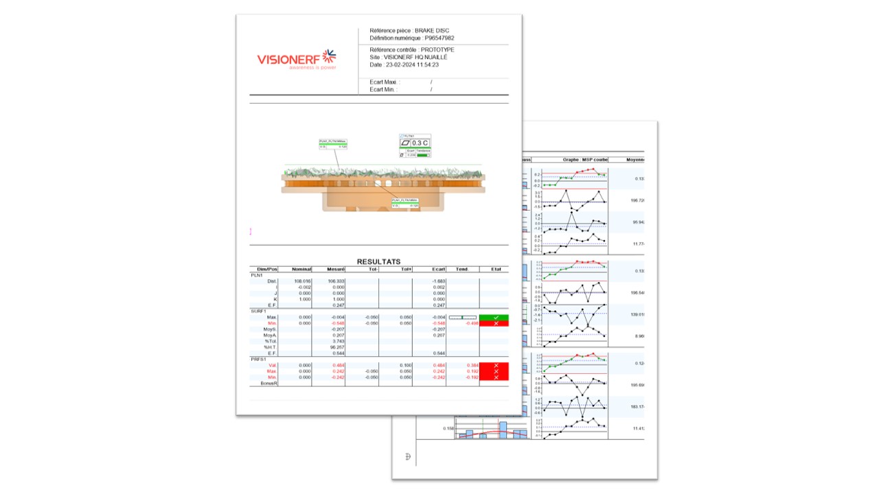
As an ultimate added value of your inspection, the inspection result can take any of the following forms on demand: it can archive results in native format, print them in a PDF report, mak a statistical analysis of your latest inspections or it can send an alert in the event of out-of-tolerance results.
Why
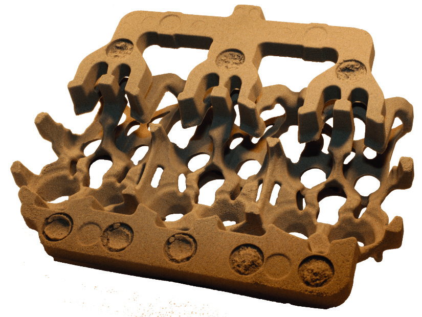
Since the first-generation Cirrus3D camera was launched in 2015, Visionerf has constantly improved its products to provide customers with a high-end scanner capable of operating in the harshest environments, such as foundries or dusty, humid environments.
The unique design of this camera, based on the principle of high-resolution stereoscopy, enables very small elements to be viewed with the utmost precision in the shortest possible time. Combined with powerful structured light, the quality of information remains constant over a wide range of materials. From black to high-gloss, measurement reliability remains flawless.
The choice of top-of-the-range components contributes greatly to the robustness and
reliability of our products.
Today, our cameras are used in all sectors of activity, for the precise handling of parts of all
sizes (screws, mechanical body parts), for robot guidance in high-volume applications (automatic detection of from potential gas leaks on refrigerators to the automatic changing of drilling tools on giant tunnel boring machines), for monitoring and inspecting objects directly on production lines.
